CR-PVS1
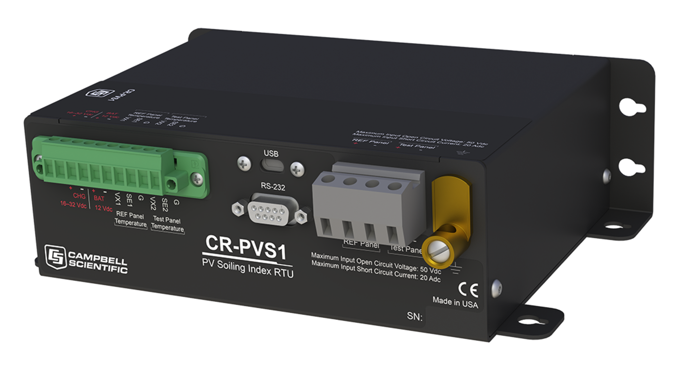
CR-PVS1
RetiredSoiling Loss Index RTU for Photovoltaic Modules
Pricing
- Model:
- CR-PVS1
- Item Number:
- 32481
- Warranty:
- 1 year
Overview
Soiling, the loss of photovoltaic (PV) module power output due to accumulation of dirt and/or snow on the panel surface, has become one of the most important operational issues of solar energy power plant performance. The CR-PVS1 Soiling Loss Index RTU provides solar energy professionals who are responsible for managing the performance of a PV power plant with the information needed to evaluate and manage the impact of soiling. Soiling loss indices are calculated using industry standard methodologies. Raw data is stored and available for additional post-processing.
Key Advantages
Providing on-board data filtering and real-time soiling loss index
Technical Description
The CR-PVS1 Soiling Loss Index RTU is designed to be at the heart of an independent soiling measurement station or as an add-on peripheral to any new or existing MET station. It supports many communication protocols such as Modbus, DNP3, PakBus, PakBus encryption, and several Internet protocols.
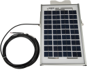
Deployment/configuration is simple and easy. The CR-PVS1 is delivered field ready and requires no programming. It will work with any user-supplied solar module to to 100 V open circuit and current up to 20 A, or it can be ordered with mini 20 W modules. Two highly accurate and rugged back-of-temperature sensors are included.
Soiling loss index is calculated from short-circuit and back-of-module temperature measurements of a reference PV module that is kept clean and a test PV module that is kept dirty. Measurements are made only when certain characteristics of global solar irradiance and temperature are met, avoiding any difference in soiling due to environmental instability, cloud influence, zenith angle of the sun, module current dependence on irradiance level, and to an extent, spectral effects. A quality factor is calculated to give the user some feedback on the number of qualified measurements.
From short-circuit current and back-of-module temperature, the effective irradiance of each module is calculated in accordance with IEC 60904 and a soiling loss index is calculated. A daily average soiling loss index is calculated, available for SCADA, and stored in on-board memory. For immediate feedback, a real-time soiling loss index and quality factor are available. Raw measured data are stored and available for the analyst or researcher looking to perform independent post-processing.
The procedure is straightforward and easily implemented with manual washing of the reference module, usually cleaned at the same time as the on-site pyranometer(s).
Short-Circuit Current Methodology
Numerous studies and documents have been published over several decades outlining and testing various methods in order to calculate losses due to soiling, along with their advantages and disadvantages. These studies show that the short-circuit current of a solar module is directly proportional to the light intensity, and it can be used as a reliable method to measure changes in light intensity from reaching the solar cells.
While other methods have been studied, such as I-V curve tracers or maximum power point trackers, these systems can provide minimal accuracy gains only under certain conditions that may not be practical in a field setting. The disadvantage to these systems is their cost and scalability, as they are typically a much more expensive and complicated endeavor.
The CR-PVS1 uses the short-circuit measurement method to provide end users with a simple, lower-cost solution that is more easily scalable and deployable in larger numbers on utility-scale solar projects using proven methods.
Benefits
- Real-time soiling loss index (SLI) measurement and control system
- On-board data filtering that assures quality data
- Daily average soiling loss index calculated
- Modbus, DNP3, PakbBus, data encyption, and Internet protocols supported
- No programming necessary
- Quick-deploy guide that simplifies installation
Specifications
- -NOTE-
- All CR-PVS1 RTUs are tested and guaranteed to meet electrical specifications in a standard -40° to +70°C non-condensing environment.
Recalibration is recommended every three years. System configuration and critical specifications should be confirmed with Campbell Scientific before purchase.
- Soiling Loss Index
- Can detect ~1%
- Maximum Voltage
- 100 V
- Maximum Current
- 20 A
- Measurement Accuracy
- ~ 2 μV
- Dimensions
- 20.3 x 14 x 6.3 cm
(8.0 x 5.5 x 2.5 in.) without mounts
- Dimensions
- 21.6 x 14 x 6.3 cm
(8.5 x 5.5 x 2.5 in.) with mounts
Back-of-Module Temperature Measurements
- Temperature Uncertainty for -40° to +70°C
- ±0.2°C tolerance
- Temperature Uncertainty for 71° to 105°C
- ±0.5°C tolerance
- Temperature Uncertainty for 106° to 135°C
- ±1°C tolerance
- Time Constant in Air
- 252 s
(still air)
- Time Constant in Air
- 25 s
(surface)
- Measurement Range
- -40° to +135°C
- Steinhart-Hart Linearization Equation Error
- 0.0024°C
(at -40°C) maximum
Short-Circuit Current Measurements
- Maximum Operating Temperature
- +80°C
- Shunt Accuracy
- ±0.25%
Communications
- Default Configuration
- Modbus RTU
- Internet Protocols
- PPP, ICMP/Ping, Auto-IP(APIPA), IPv6, UDP, TCP, TLS, DHCP Client, SLAAC, DNS Client, Telnet
- Additional Protocols Supported
- PakBus, SDI-12, Modbus RTU, Modbus ASCII, Modbus TCP/IP, DNP3
(Custom user-definable over serial.)
- Data File Formats
- CSV, XML, JSON, binary, encrypted
- USB
- USB micro-B device only, 2.0 full-speed 12 Mbps, for computer connection
- RS-232
- Female RS-232, 9-pin interface
System
- Clock Accuracy
- ±1 min per month
- Clock Resolution
- 1 ms
- Program Execution
- 100 ms to one day
Power Requirements
- Charger Input (CHG)
- 16 to 32 Vdc, current limited at 0.9 A
(power converter or solar panel input)
- Internal Lithium Battery
- 3 V coin cell CR2016 (Energizer) for battery-backed clock.
(6-year life with no external power source)
- External Batteries (BAT)
- 12 Vdc, lead-acid 7 Ah battery
(typical)
- USB Power (USB)
- For programming and limited functionality
- Typical Power Requirements
- 1.5 mA
(sleep)
- Typical Power Requirements
- 5 mA
(active 1-Hz scan with analog measurements)
Compliance
- CE
- All terminals tested to Class 4 levels (IEC 61000-4-5: 2013) for surge and (IEC 61000-4-2:2008) for ESD.
- Shock & Vibration
- ASTM D4169-09
- Protection
- IP30
Accessories
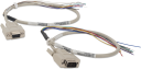
(14)SC110
Two Cables, RS-232 to Data Logger Control Port
OrderableMD485
RS-485 Multidrop Interface
OrderableNL201
Network Link Interface
OrderableRV50
Industrial 4G LTE Cellular Gateway
RetiredSP10
10 W Solar Panel
OrderableSP20
20 W Solar Panel
OrderableSP50
50 W Solar Panel
OrderableSP90
90 W Solar Panel
Orderable44157
3.8 A 24 V NEC Class 2 Power Supply Kit
OrderableBP7
7 Ah 12 V Sealed Rechargeable Battery
OrderableBP12
12 Ah 12 V Sealed Rechargeable Battery with Mounts
OrderableBP24
24 Ah 12 V Sealed Rechargeable Battery
OrderableBP84
84 Ah 12 V Sealed Rechargeable Battery
OrderableCABLEPCBL
2-Conductor 16 AWG Power Cable
Orderable