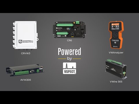
AVW211

AVW211
RetiredConfigurable922 MHz Wireless 2-Channel Vibrating Wire Analyzer Module
Pricing
Configuration
Sign in for option pricing- AVW211 922MHz Wireless 2-Channel Vibrating Wire Spectrum Analyzer ModuleAVW211
- 922MHz Wireless 2-Channel Vibrating Wire Spectrum Analyzer Module -ST -25 to +50C 1. AVW211 PTO 922MHZ WI 2. AVW211 922MHZ WIRELE922MHz
Select a configuration to add to your quote
- Model:
- AVW211
- Item Number:
- 20750
- Warranty:
- 1 year
- Lead time:
- 14 days
Overview
The AVW211 is a vibrating wire analyzer module that includes an internal 920 to 928 MHz spread-spectrum radio for wireless communication, typically used in Australia and New Zealand. With this vibrating wire analyzer module, your data logger can measure vibrating wire strain gages, pressure transducers, piezometers, tiltmeters, crackmeters, and load cells. These sensors are used in a wide variety of structural, hydrological, and geotechnical applications because of their stability, accuracy, and durability.
Key Advantages
Includes built-in radio
Technical Description
The AVW211 uses vibrating wire spectral-analysis technology (VSPECT™). VSPECT observes the incoming sensor signal, performs a Fourier transform and a spectral analysis (transforming the time series into individual sinusoidal components in the frequency spectrum), and determines the sensor frequency by identifying the largest signal in the acceptable range while filtering out environmental and electrical noise.
The AVW211 analyzer module also provides many self-checking diagnostics such as vibrating element signal strength, signal-to-noise ratio, vibrating element signal decay ratio, and incorrect signal response. These diagnostics can be running in the background to give continual feedback of the condition for each sensor.
The AVW211 typically transmits its data to an RF411A spread-spectrum radio that is connected to the data logger. The AVW211 can also be connected directly to the data logger.
Benefits
- Provides better measurements by significantly reducing incorrect readings caused by noise sources
- Interfaces two vibrating wire sensors; more sensors may be connected if an AM16/32B multiplexer is used
- Self-checking diagnostics give continual feedback on sensor condition
- High resolution—less than 0.001 Hz (industry standard is 0.1 Hz)
- Low current drain
- Remote, wireless operation with on-board radio
- Interfaces both temperature and frequency measurements from vibrating wire sensors
Specifications
- -NOTE-
- Electrical specifications are valid over a -25° to +50°C range unless otherwise specified. Non-condensing environment required.
- Internal Radio Frequency Range
- 920 to 928 MHz
- Radio Power
- 250 mW
Older AVW211 analyzer modules (serial # < 11676) have 100 mW radios. - Number of Vibrating Wire Sensors Measured
- Up to 2 vibrating wire sensors can be connected to the analyzer module.
Additional sensors can be measured by using an AM16/32-series multiplexer.
- Power Requirements
- 9.6 to 16 Vdc
- Analog Input/Outputs
- 2 differential (DF) vibrating wire measurements (V+ and V-) and 2 single-ended (SE) ratiometric resistive half-bridge measurements (T+ and T-) for vibrating wire sensor's onboard temperature sensor.
- Digital Control Ports
- 3 digital control ports (C1 – C3)
C1 functions as an SDI-12 I/O communication port.C2 functions as a Clk output for multiplexer control.C3 functions as a Reset output for multiplexer control.
- RS-232 Port
- 1 9-pin RS-232 port
(for connecting to a data logger COM port)
- Measurement Resolution
- 0.001 Hz RMS
(±250 mV differential input range; -55° to +85°C)
- Measurement Accuracy
- ±0.013% of reading
(±250 mV differential input range; -55° to +85°C)
- Input Voltage Range
- ±250 mV
(differential) for vibrating wire inputs
- Common Mode Range
- ±25 V
- Baud Rates
- Selectable from 1200 to 38.4 kbps
(ASCII protocol is one start bit, one stop bit, eight data bits, and no parity.)
- Memory
- Either 128 or 512 kB of SRAM
- Memory
- 2 MB of OS Flash
- CE Compliance Standards to which Conformity Is Declared
- EC61326:2002
- Dimensions
- 21.6 x 11.18 x 3.18 cm
(8.5 x 4.5 x 1.2 in.)
- Weight
- 0.43 kg
(0.95 lb)
Typical Current Drain @ 12 Vdc
- Quiescent, Radio Off
- ~0.3 mA
- Radio Duty Cycling 1 s
- ~3 mA
(includes quiescent current)
- Radio Always On
- ~26 mA
(radio transmit current 100 mA)
- Active RS-232 Communication
- ~6 mA
(3 s after communication stops, the current will drop to the quiescent current)
- Measurement
- ~25 mA
(averaged over the 2 s)
Accessories
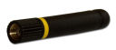
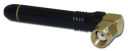
(9)14204
900 MHz 0 dBd 1/2 Wave Omnidirectional Antenna with RPSMA Connector
Orderable15970
900 MHz 1 dBd Omnidirectional Dipole Antenna with Adhesive Mount
Orderable14201
900 MHz 9 dBd Yagi Antenna with Mounting Hardware
Orderable14221
900 MHz 3 dBd Omnidirectional Antenna with Mounting Hardware
Orderable15731
900 MHz 0 dBd 1/4 Wave Omnidirectional Antenna with RPSMA Connector
Orderable15730
900 MHz 0 dBd 1/4 Wave Omnidirectional Antenna with RPSMA Connector
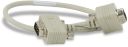
Orderable18663
Null Modem Cable, 9-Pin PIn (Male) to 9-Pin Pin (Male)
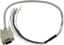
Orderable17855
Serial Cable, DB9 Pin (Male) to Pigtail
OrderableCABLE3CBL
3-Conductor 22 AWG Cable with Drain
Orderable

Related Resources
Documents
- Manual
AVW200-series 2-Channel Vibrating Wire Spectrum Analyzer Modules
February 2025
View Document - Brochure
AVW200-series Vibrating Wire Modules
February 2010
View Document - Brochure
Vibrating Wire Spectral-Analysis Technology (VSPECT)
April 2017
View Document - Document
AVW206, AVW211, and AVW216 Discontinuation Notice
August 2023
View Document - View all documents