CSAT3BH
CSAT3BH
OrderableConfigurableGSAHeated, 3-D Sonic Anemometer with Integrated Electronics
Pricing
Configuration
Sign in for option pricing- No Carrying CaseCSAT3BH-NC
- Sonic Carrying CaseCSAT3BH-SC
Select a configuration to add to your quote
- Model:
- CSAT3BH
- Item Number:
- CSAT3BH
- Warranty:
- 1 year
- Lead time:
- 14 days
Overview
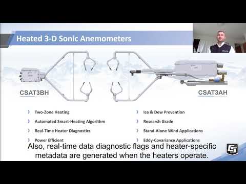
The CSAT3BH is ideal for stations that are deployed in cold climates. The easy-to-use CSAT3BH sonic anemometer features smart heating that delivers just the right amount of heat to keep the instrument free of ice and snow, enabling continuous and reliable measurements in cold environments. The CSAT3BH is designed to prevent ice accumulation on the sensor, avoiding prolonged periods of data loss.
The CSAT3BH features variable power, only delivering power when needed—as opposed to the common method of providing two-way heating (on/off). Moreover, there are real-time data flags when the heaters are turned on, which is crucial to post-processing your data files.
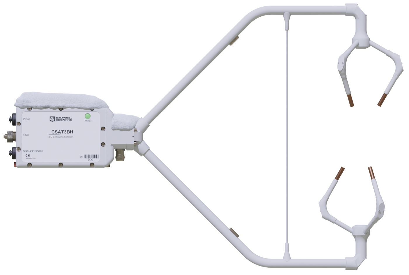
The CSAT3BH is a heated version of the CSAT3B 3-D Sonic Anemometer with Integrated Electronics. The specifications of the CSAT3BH are the same as the CSAT3B with regard to wind measurements.
Key Advantages
Provides continuous, reliable data year-round in harsh environments
Technical Description
The CSAT3BH provides integrated two-zone smart heating:
- Zone 1 consists of the arms and strut.
- Zone 2 provides heating to all the transducers.
The smart heating uses environmental conditions and a controller to apply variable heating to the sonic anemometer to keep the body and transducers free of ice and snow. The CSAT3BH is designed to prevent ice from forming on the arms and fingers of the system. The block has no heating in it. The CSAT3BH has a separate controller that is used to control the heating algorithm of the sensor. The controller requires a temperature/RH input. There is an ambient temperature and relative humidity sensor that is standard for use with the controller, or the data can be provided through a user-supplied temperature/RH sensor.
Physical
The CSAT3H heater controller is a polycarbonate enclosure sized 20.32 x 25.4 x 15.24 cm (8 x 10 x 6 in.). The enclosure uses connectors for incoming power, heaters, temperature sensors, temperature/RH, RS-485(2), and USB.
Electrical
The heaters are controlled on two zones and require 150 W at full power. The controller controls the heaters by increasing or decreasing the voltage to get the appropriate wattage to keep ice from forming on the sensor.
Benefits
- New conformal coating helps protect sonic transducers in corrosive environments
- Two-zone heating to keep both the transducers and body of the sonic anemometer free of snow and ice
- Heating controller using environmental feedback to ensure power budgeting
- Streamlined heater integration to ensure maintenance of sonic aerodynamics
- Integrated data flagging, providing critical information when heaters were operational
Specifications
- Sensor
- 3-dimensional sonic anemometer
- Measurement Description
- Highest-quality wind speed and direction
- Operating Temperature Range
- -40 to +50°C
(equivalent to 305 to 368 m s-1 in speed of sound)
- Outputs
- ux, uy, uz, Ts
(ux, uy, uz are wind components referenced to the anemometer axes; Ts is sonic temperature in degrees Celsius.)
- Speed of Sound
- Determined from three acoustic paths.
(Corrected for crosswind effects.)
- Wind Direction Range
- 2.5 to 357.5° in CSAT3B coordinate system
(0 to 360° customized)
- Filter Bandwidths
- 5, 10, 20, or 25 Hz
- Measurement Path Length
- 10.0 cm (3.9 in.) vertical; 5.8 cm (2.3 in.) horizontal
- Transducer Angle from Horizontal
- 60 degrees
- Transducer Diameter
- 0.64 cm
(0.25 in.)
- Transducer Mounting Arm Diameter
- 0.84 cm
(0.33 in.)
- Support Arm Diameter
- 1.59 cm
(0.63 in.)
- Anemometer Head Weight
- 1.9 kg
(4.2 lb)
- Anemometer Dimensions
- 63.1 x 12.3 x 43.3 cm
(24.8 x 4.9 x 17.0 in.)
Power Requirements
- Anemometer Voltage Requirement
- 9.5 to 32 Vdc
- Current Required for 10 Hz Measurement Rate
- 110 mA
(@ 12 Vdc)
- Current Required for 10 Hz Measurement Rate
- 65 mA
(@ 24 Vdc)
- Current Required for 100 Hz Measurement Rate
- 145 mA
(@ 12 Vdc)
- Current Required for 100 Hz Measurement Rate
- 80 mA
(@ 24 Vdc)
- Heaters
- 6.2 A
(@ 24 Vdc)
- Arms and Strut
- 0.74 A nominal
(@ 24 Vdc)
- Arms and Strut
- 2.46 A at maximum heating
(@ 24 Vdc)
- Transducer Fingers
- 1.13 A nominal
(@ 24 Vdc)
- Transducer Fingers
- 3.75 A at maximum heating
(@ 24 Vdc)
- Total System Power
- 1.86 A nominal
(@ 24 Vdc)
- Total System Power
- 6.2 A at maximum heating
(@ 24 Vdc)
- Controller Current Required
- 30 mA
(heaters off [quiescent] @ 24 Vdc)
Wind Accuracy
- -NOTE-
- Accuracy specifications assume the following:
-40° to +50°C operating rangeWind speeds < 30 m s-1Wind angles between ±170°
- Maximum Offset Error
- < ±8.0 cm s-1 (ux, uy), < ±4.0 cm s-1 (uz)
- Maximum Gain Error
- < ±2% of reading
(wind vector within ±5° of horizontal)
- Maximum Gain Error
- < ±3% of reading
(wind vector within ±10° of horizontal)
- Maximum Gain Error
- < ±6% of reading
(wind vector within ±20° of horizontal)
Measurement Resolution
- ux, uy
- 1 mm s-1 RMS
- uz
- 0.5 mm s-1 RMS
- Ts
- 0.002°C RMS
(at 25°C)
- Wind Direction
- < 0.058°
(ux = uy ≤ 1 m s-1)
Measurement Rates
- Data Logger Triggered
- 1 to 100 Hz
- Unprompted Output (to PC)
- 10, 20, 50, or 100 Hz
- Internal Self-Trigger Rate
- 100 Hz
Measurement Delay
- Data Logger Triggered (no filter)
- 1 trigger period
(1 scan interval)
- Unprompted Output (no filter)
- 10 ms
- Filtered Output (data-logger-prompted or unprompted to PC)
- 795 ms
(with 5 Hz bandwidth filter)
- Filtered Output (data-logger-prompted or unprompted to PC)
- 395 ms
(with 10 Hz bandwidth filter)
- Filtered Output (data-logger-prompted or unprompted to PC)
- 195 ms
(with 20 Hz bandwidth filter)
- Filtered Output (data-logger-prompted or unprompted to PC)
- 155 ms
(with 25 Hz bandwidth filter)
Internal Monitor Measurements
- Update Rate
- 2 Hz
- Inclinometer Accuracy
- ±1°
- Relative Humidity Accuracy
- ±3%
(over 10 to 90% range)
- Relative Humidity Accuracy
- ±7%
(over 0 to 10% range)
- Relative Humidity Accuracy
- ±7%
(over 90 to 100% range)
- Board Temperature Accuracy
- ±2°C
SDM
- -NOTE-
- Used for data-logger-based data acquisition.
- Bit Period
- 10 µs to 1 ms
- Cable Length
- 7.6 m (25 ft) max
(@ 10 µs bit period)
- Cable Length
- 76 m (250 ft) max
(@ 1 ms bit period)
- Address Range
- 1 to 14
- Bus Clocks per Sample
- ~200
CPI
- -NOTE-
- Used for data-logger-based data acquisition.
- Baud Rate
- 50 kbps to 1 Mbps
- Cable Length
- 15 m (50 ft) max
(@ 1 Mbps)
- Cable Length
- 122 m (400 ft) max
(@ 250 kbps)
- Cable Length
- 853 m (2800 ft) max
(@ 50 kbps)
- Address Range
- 1 to 120
- Bus Clocks per Sample
- ~300
RS-485
- -NOTE-
- Used for anemometer configuration or PC-based data acquisition.
- Baud Rate
- 9.6 kbps to 115.2 kbps
- Cable Length
- 305 m (1000 ft) max
(@ 115.2 kbps)
- Cable Length
- 610 m (2000 ft) max
(@ 9.6 kbps)
- Bus Clocks per Sample
- ~500
(ASCII formatted)
USB
- -NOTE-
- Used for anemometer configuration or PC-based data acquisition.
- Connection Speed
- USB 2.0 full speed 12 Mbps
- Cable Length
- 5 m (16.4 ft) maximum
Accessories
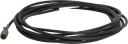
(19)CSAT3BCBL2
Power-Only Cable for CSAT3B
OrderableCSAT3BCBL3
CPI/RS-485 Cable for CSAT3B
OrderableCSAT3HCBL2
CSAT3H Control Box RS-485 RX Cable
OrderableCSAT3HCBL1
Control Box RS-485 TX/RX Cable for CSAT3BH
OrderableCSAT3HCBL3
Control Box Power Cable for CSAT3BH
OrderableCSAT3BCBL1
Power/SDM Cable for CSAT3B
OrderableCSAT3HCBL2
CSAT3H Control Box RS-485 RX Cable
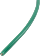
Orderable4335
10 AWG Green Copper Stranded Wire
Orderable10080
Thermocouple Cover for CSAT3, CSAT3B, or IRGASON
Orderable31423
Fine-Wire Thermocouple Cover Backplate
OrderableFW05
Type E Fine-Wire Thermocouple with 0.0005 in. Diameter
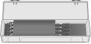
OrderableFW/ENC
Fine-Wire Thermocouple Carrying Case (hold four thermocouples)
OrderableFWC
Connector Cable for Fine-Wire Thermocouples
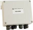
OrderableHUB-SDM8
8-Channel Hub for SDM Peripherals and Power Connections
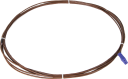
OrderableCABLE5CBL
5-Conductor 22 AWG Cable with Drain
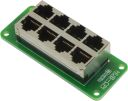
OrderableHUB-CPI
8-Channel RJ45 Hub for CPI Peripherals
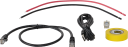
Orderable29370
CPI Network Kit
Orderable28899
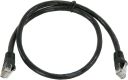
CAT6 Ethernet Unshielded Cable with RJ45 Connectors, 2 ft
Orderable38476
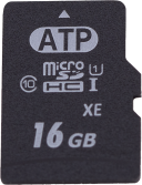
16 GB microSD Flash aMLC Memory Card
Orderable




Related Resources
Documents
- Document
Weather-condition-regulated, heated 3-D sonic anemometers (CSAT3AH and CSAT3BH): Working rationale, operation algorithm, and performance assessment
April 2021
View Document - Manual
CSAT3BH Quick Deploy Guide
February 2020
View Document - Manual
CSAT3BH Packing Information
November 2019
View Document - Compliance
CSAT3BH EU Declaration of Conformity
March 2020
View Document - View all documents