RF416
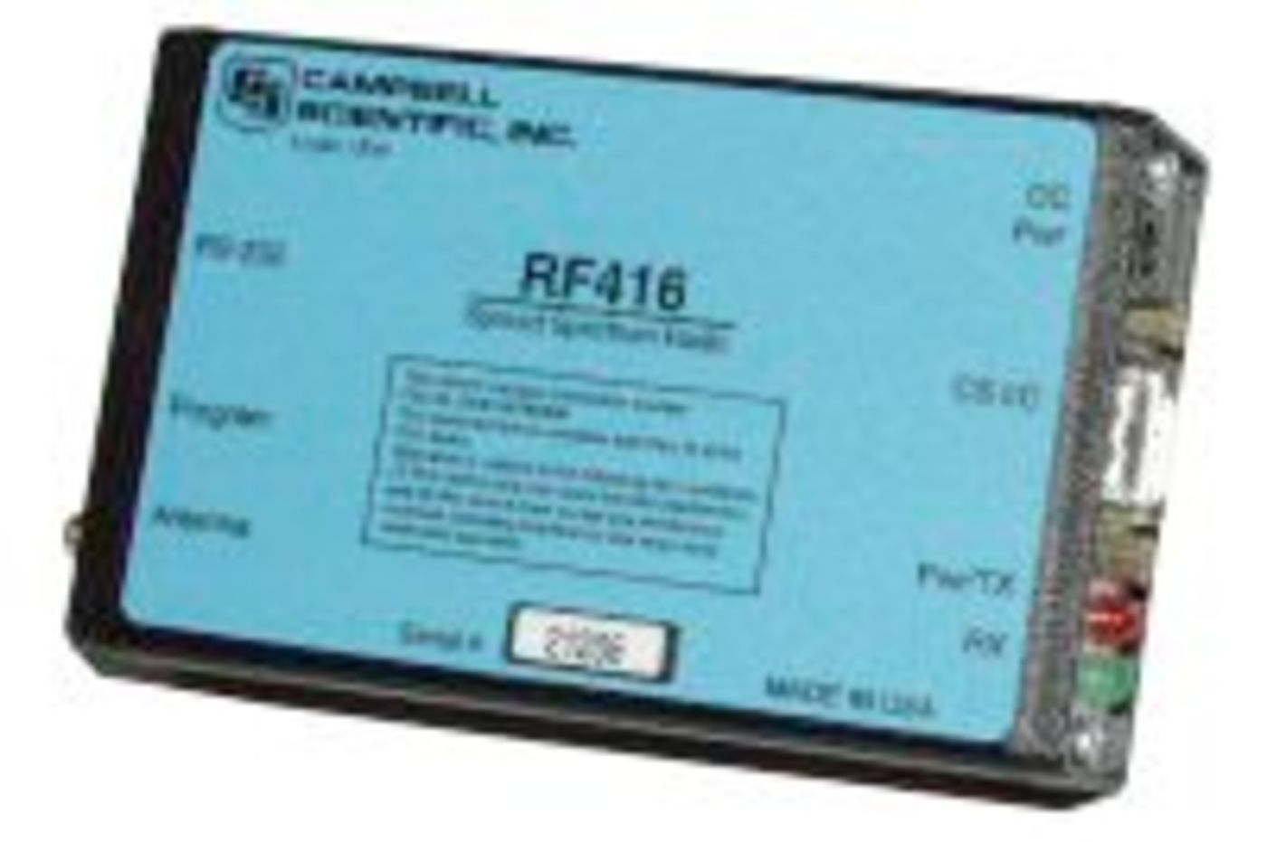
RF416
Retired2.4 GHz Spread-Spectrum Radio
Pricing
- Model:
- RF416
- Item Number:
- 18105
- Warranty:
- 1 year
- Lead time:
- 7 days
Overview
The RF416 spread-spectrum radio can be used for general purpose wireless data communication and supports point-to-point and point-to-multipoint data logger communication. It can serve as a field modem/radio while connected to the data logger or as a base station modem/radio when connected to a computer.
The RF416 has a frequency range of 2.450 to 2.482 GHz, which is used in many countries worldwide. It can communicate with other RF416 radios, and RF432 radios, as well as the internal radio in CR216(X) dataloggers and AVW216 interfaces.
Note: The operating frequency band of this radio modem may be shared with other non-licensed services such as cordless telephones and with licensed services including emergency broadcast and air-traffic control.
Technical Description
Spread-spectrum radios spread the normally narrowband information signal over a relatively wide band of frequencies. This allows the communications to be highly immune to noise and interference from RF sources such as pagers, cellular phones, and multipath. The RF416 reduces susceptibility to RF interference from other spread-spectrum devices by providing user-selectable frequency-hopping patterns.
Spread spectrum radios, like all FCC Part 15 devices, are not allowed to cause harmful interference to licensed radio communications and must accept any interference that they receive. Most Campbell Scientific users operate in open or remote locations where interference is unlikely. If there is a problem, interference can be reduced using methods such as moving the device, reorienting or using a different type of antenna, or adding RF shielding.
Powering the Radio
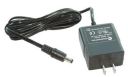
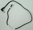
At the base station, the RF416 is powered using the 15966 wall charger. At the field site, the RF416 is typically powered by the data logger through the CS I/O port. The #14291 Field Cable is required at the field site for the following situations:
- Radio connected to the data logger’s RS-232 port instead of the CS I/O port
- Data logger purchased before December 1997
Antennas
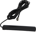
Campbell Scientific offers a variety of antennas for this radio. The 16005 is an omnidirectional 1/2-wave, 0 dBd, whip antenna that connects directly to the radio (no cable required) and can transmit short distances (up to 1 mile). The 17480 dipole antenna includes adhesive for window or wall mounting and a cable for connecting to the radio.
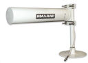
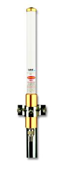
Our higher gain 30411 omnidirectional and 16755 Yagi antennas require a cable to connect them to the radio. The 31314 surge protector is available for radios susceptible to lightning or electrostatic buildup or when the cable length needs to be longer than 3 m (10 ft), as measured between the transceiver and the antenna.
Benefits
- Long range, wireless communications between devices
- Hassle-free operation in many countries where license-free operation is allowed
- Low average power consumption
- Optimized for Campbell Scientific PakBus networking
- Improved RF efficiency when using PakBus protocol compared to other third-party solutions
- Low-cost, stand-alone operation when a dedicated PakBus RF repeater is needed
- Frequency hops over 25 channels avoid interference from other spread-spectrum radios
Specifications
- Frequency
- 2.450 to 2.482 GHz
- Radio Type
- Frequency Hopping Spread Spectrum (FHSS)
- Country Used In
- FCC-certified module for the USA
- Transmission Distance
- 0.4 km (0.25 mi) with omnidirectional antenna (outdoors); up to 0.8 km (0.5 mi) with higher-gain directional antennas at ideal conditions
- RS-232 Baud Rate
- 38.4k, 19.2k, 9600, 4800, or 1200 bps
- Channel Capacity
- 65,000 Network Identifiers share 25 hop channels.
- Frequency Hopping Patterns
- 6 different selectable patterns
- Frequency Control
- Direct FM
- Receiver Sensitivity
- -104 dBm at 10-4 bit error rate
(Campbell Scientific protocols will issue retries wherever a bit error occurs.)
- Interference Rejection
- 70 dB
(at pager and cellular phone frequencies)
- Power Output
- 50 mW
(nominal)
- Data Rate
- 10 kbps
- Antenna Connector
- Reverse Polarity SMA (RPSMA)
- RS-232 Connector
- 9-pin D female
(4 wire: Tx, Rx, CTS, GND)
- CS I/O Connector
- 9-pin D male
- FCC ID
- OUR-24XSTREAM
- Power
- 9 to 16 Vdc
- Operating Temperature Range
- -25° to +50°C
- LEDs
- Power on, TX, RX, diagnostics
- Power Connector
- Barrel plug, center positive 12 V
(used to connect the 14291 Field Power Cable)
- Average Current Drain
- < 1 mA
(standby with power-saving options used)
- Average Current Drain
- 36 mA
(receiving)
- Average Current Drain
- 75 mA
(transmitting)
- Communication Ports
- RS-232 9-pin D female
(4 wire: Tx, Rx, CTS, GND)
- Communication Ports
- CS I/O 9-pin D male
(Newer data loggers provide power to the radio on this connector. Data loggers purchased before December 1997 require the pn 14291 Field Power Cable.)
- Dimensions
- 11.4 x 7.0 x 2.9 cm
(4.5 x 2.8 x 1.1 in.)
- Weight
- 227 g
(8 oz)
Accessories
(11)16005
2.4 GHz 0 dBd Omnidirectional 1/2 Wave Whip Antenna
Orderable15966
Wall Charger with Barrel Plug
Orderable14291
Field Power Cable, 12 Vdc Plug to Pigtail
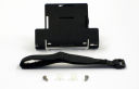
Orderable14162
RF401, RF411, or RF416 Mounting Kit
Retired16755
2.4 GHz 13 dBd Yagi Enclosed Antenna with Mounting Hardware
Orderable17480
Tri-Band 1 dBd Omnidirectional Antenna with RPSMA Connector and Adhesive Mount
Limited availability30411
2.4 GHz 5.8 dBd Omnidirectional Fiberglass Antenna without Mounting Hardware
Orderable13906
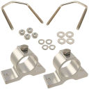
Mount for Fiberglass Antenex Omnidirectional Antennas
Orderable18663
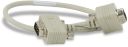
Null Modem Cable, 9-Pin PIn (Male) to 9-Pin Pin (Male)
Orderable14413
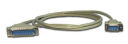
RS-232 Cable, DB9 Pin (Male) to DB25 Pin (Male)
End of life16987
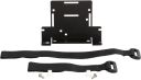
Peripheral Mounting Kit
Orderable

Related Resources
Documents
- Technical Paper
RF401-to-CR206 Communications: Quick Reference Guide
November 2009
View Document - Technical Paper
Line of Sight Obstruction
October 2016
View Document - Technical Paper
The Link Budget and Fade Margin
September 2016
View Document - Manual
RF401-series and RF430-series Spread Spectrum Data Radios/Modems
April 2017
View Document - View all documents