AL200X
AL200X
OrderableALERT and ALERT2 Modem and Sensor Interface
Overview
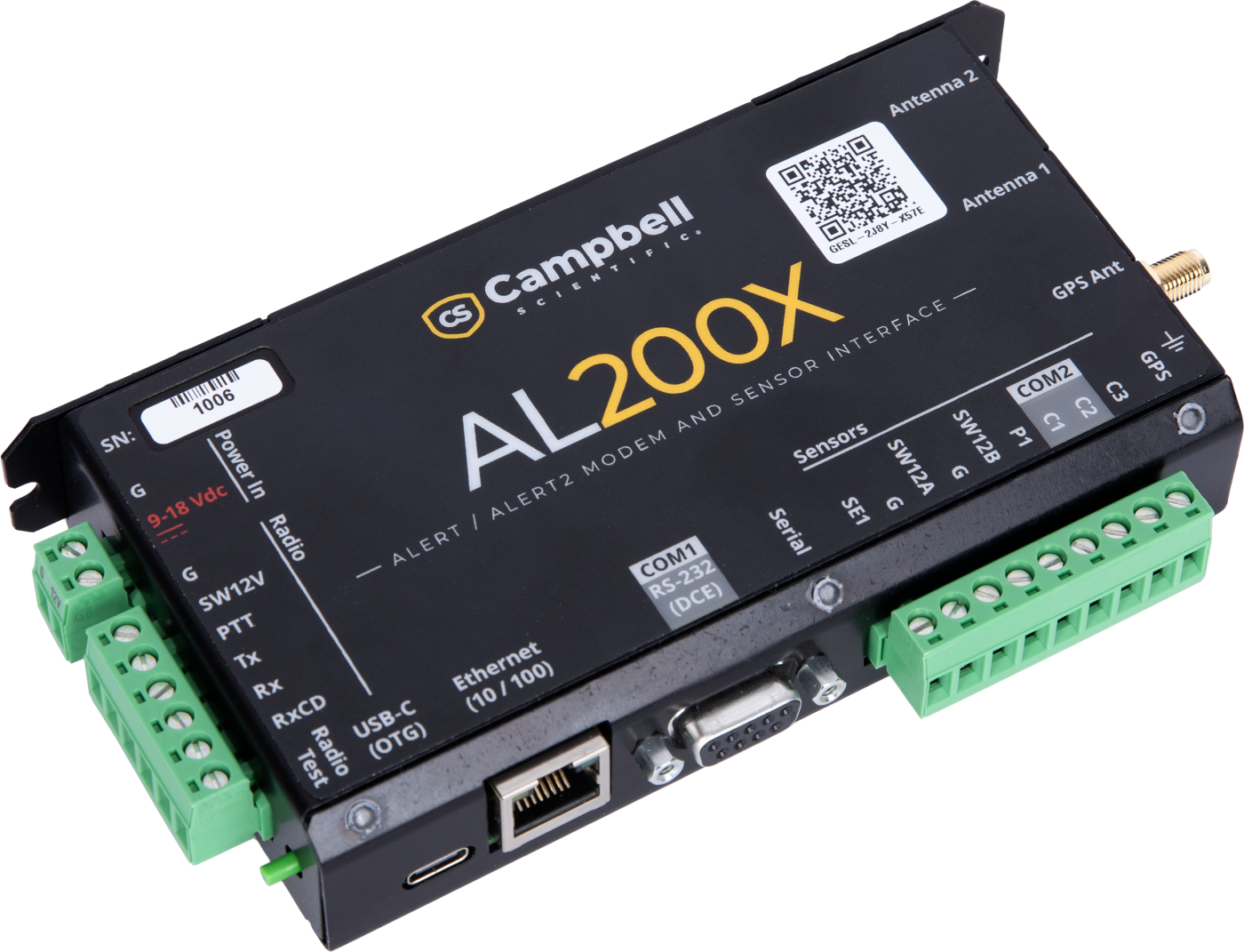
The AL200X is an ALERT and ALERT2 modem and sensor interface designed for critical flood warning weather systems. It complies with the ALERT and ALERT2 standards maintained by the National Hydrologic Warning Council (NHWC) and the ALERT Users Group (AUG).
Built to support both legacy and modern systems, the AL200X allows you to continue operating your existing ALERT field stations while preparing for the future. When you're ready, upgrading to ALERT2 can be done on your own timeline with a simple setting change in the user interface.
Transitioning to ALERT2 unlocks significant performance advantages, including faster data transfer, forward error correction, and a time division multiple access (TDMA) architecture that enhances the overall accuracy and reliability of flood warning systems and software.
With integrated sensor inputs and outputs, the AL200X enables you to create a minimal ALERT or ALERT2 transmitter/station, decreasing the cost of a typical flood warning system. Internal storage provides data logging capabilities to enhance troubleshooting and maintenance activities. The switched 12 volt and control ports can be configured to provide logic for control of other devices, such as warning beacons. Combining the AL200X with a Campbell Scientific data logger provides enhanced sensor support and extended telemetry options.
Key Advantages
Technical Description
Terminal Descriptions
- SE1: One single-ended analog input to measure 0 to 5 Vdc or 4 to 20 mA sensors
- P1: One pulse port for measuring tipping bucket rain gauges
- C1, C2, and C3: Three digital I/O control ports that can be configured for SDI-12 as separate buses (standard and watch modes), digital input, or digital output
- SW12A and SW12B: Two switched 12 Vdc power outputs that can be programmed to power sensors on and off
- G: Two grounding ports
Operating Modes
The AL200X can be configured to operate in measurement and control mode as a stand-alone device or in Intelligent Network Device (IND) mode to connect to an external device, such as a data logger.
- The measurement and control mode activates the sensor input and output ports to operate as an ALERT2 transmitter.
- The IND mode allows connection to a data logger through the COM1 RS-232 interface for expanded sensor and telemetry device support.
Both configuration modes use the integrated radio and GPS interfaces.
Configuration
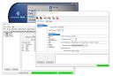
Easily configure the AL200X with the familiar Device Configuration (DevConfig) software utility. The intuitive user interface enables you to easily set up and maintain a station, spending less time in the field. You can configure the sensor input and output in either basic or advanced mode, providing flexible control over the device. The provided data monitor helps you view the current system data and the past three measurements. The command terminal offers powerful control over the AL200X, enabling access to raw sensor traffic, data logs, and SDI-12 sensor configuration, in addition to other features.
Benefits
- Minimize setup time with easily configurable user software.
- Upgrade networks over time using ALERT and ALERT2 compatibility.
- Reduce system costs with integrated sensor inputs and data logging.
- Generate event- or schedule-driven reports for battery, clock, tipping bucket, voltage, current, SDI-12, and high/low state.
- Decrease field time with quick-access features for initiating sensor test transmissions, testing radio power, and checking antenna (VSWR) performance.
- Ensure data integrity with encrypted ALERT2 messages.
- Support 250-millisecond slots and configurable forward error correction to enable high data-rate transmissions over strong RF paths.
Specifications
- Operating Temperature
- -40° to +60°C
(-40° to +140°F)
- Operating Temperature
- Non-condensing environment
- Case Material
- Anodized aluminum
- Analog Input
- One single-ended (SE1), selectable 0 to 5 Vdc or 4 to 20 mA
- Analog Input
- 16-bit ADC resolution
- Pulse Counter
- One pulse or switch closure (P1) with 16-bit counter
- Pulse Counter
- 100 Hz maximum count rate, 100 kΩ pull-up to 5 Vdc
- Digital I/O
- Three terminals (C1 to C3) configurable for digital input, output, or SDI-12
- Digital I/O
- Up to three independent SDI-12 channels
- Digital I/O
- 0 to 5 Vdc digital I/O, 200 kΩ pull-down
- Switched 12 Volt
- Two terminals
- Switched 12 Volt
- Current limit 0.9 A @ +20°C per terminal
- Switched 12 Volt
- Reverse polarity protected
- Communications Ports
- USB-C
- Communications Ports
- RS-232 (COM1)
- Power Requirements
- 9 to 18 Vdc input
- Power Requirements
- Reverse polarity protected
- Current Drain
- 6.8 mA
(@ 12 Vdc average when idle)
- Current Drain
- + 19 mA additional
(@ 12 Vdc GPS active with typical 20 mA GPS antenna)
- Current Drain
- + 7 mA additional
(@ 12 Vdc during transmit)
- GPS Antenna Connection
- SMA socket connector
- GPS Antenna Connection
- Active or inactive antennas supported, 25 dB max gain
- GPS Antenna Connection
- Active antenna power 3.2 Vdc @ 50 mA
(maximum)
- System Timekeeping
- 60 PPB (0.06 PPM) clock drift typical
(-40° to +60°C)
- System Timekeeping
- Internal UTC accuracy of 5 ms/day without continuous GPS synchronization derived from a precision TCXO tracking loop
- Radio Interface
- ALERT2 communications protocol
- Radio Interface
- Tx audio, PTT, switched power, ground
- Radio Interface
- Tx audio level adjustable from 100 to 1,000 mVpp
- Radio Interface
- Programmable warm-up, carrier only, Automatic Gain Control (AGC), and RF tail time intervals
- Data Storage
- 128 MB on-board flash
- Test Button
- Initiates a 1 kHz transmit tone or self-report transmission
- Dimensions
- 15.9 x 7.7 x 2.8 cm
(6.3 x 3.0 x 1.09 in.)
- Weight
- 249 g
(0.55 lb)
Standards
- ALERT2
- IND API specification v2.1 draft
- ALERT2
- AirLink v1.2 draft
- ALERT2
- MANT v1.2
- ALERT2
- Application Layer Protocol v1.3, rev. E
- Compliance
- RoHS 2: EN IEC 63000:2018
- Compliance
- Emissions: FCC Part 15
Accessories
(12)43342
Two-Year Extended Warranty for the AL200X
Orderable17992
28 dBi 3.3 V active GPS Antenna without Cable
Orderable31326
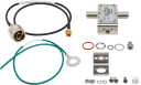
Surge Protection Kit, GPS Antenna Type N to SMA
Orderable31182
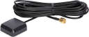
27 dBi GPS Antenna with 3 V Magnetic Mount and SMA Connector
Orderable45005
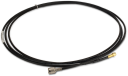
GPS Antenna Cable
Orderable30626
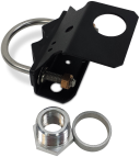
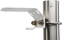
3/4 in. IPS or GPS Antenna Mounting Stand
OrderableCM235
Magnetic Mounting Stand
Orderable8125
Flat-Bladed Screwdriver, 2.5 mm Blade x 50 mm Shaft
OrderableALERT2ADM
ALERT2 Administrator (requires LoggerNetADM)
Orderable10873
Serial Data Cable, 9-Pin Socket (Female) to 9-Pin Pin (Male)
Orderable21212
Black Cold Shrink Tape
Orderable19329
Coaxial Cable, Type N Bulkhead to SMA
Orderable



Related Resources
Documents
- Brochure
AL200X ALERT and ALERT2 Modem and Sensor Interface
April 2026
View Document - Manual
AL200X Product Manual (online)
April 2026
View Document - Document
AL200X: Heart of ALERT2 Flood Warning Systems
June 2025
View Document - Manual
AL200X ALERT and ALERT2 Encoder, Modulator, and Sensor Interface
April 2026
View Document