CH200
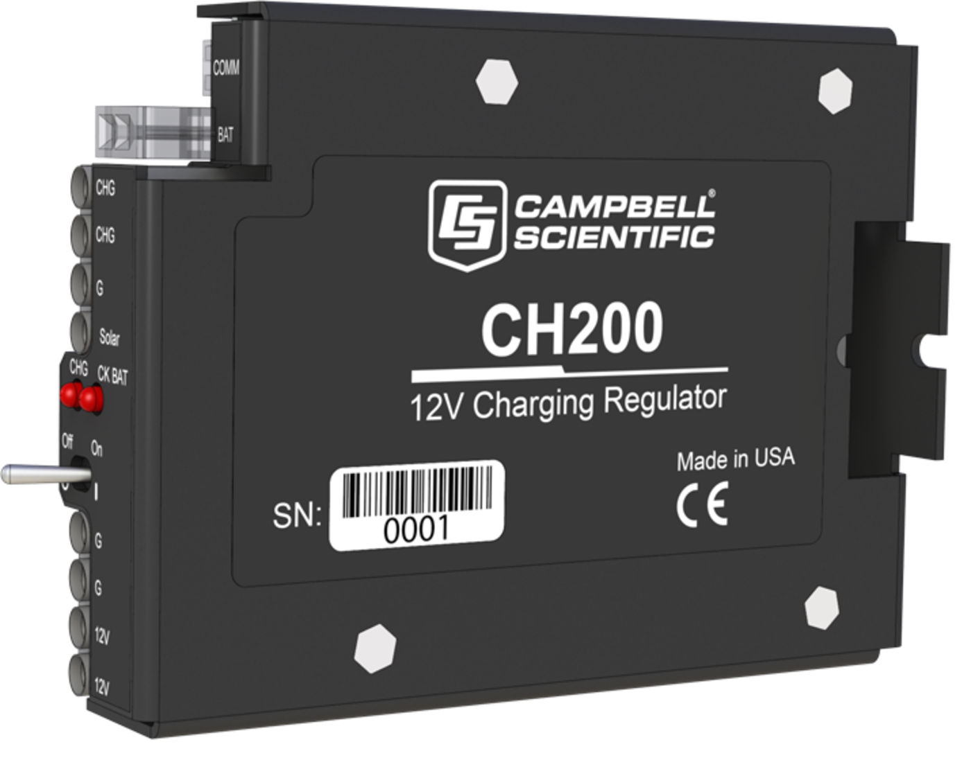
CH200
OrderableSmart 12 V Charging Regulator
Best for general applications with power system monitoring.
Pricing
- Model:
- CH200
- Item Number:
- 22240
- Warranty:
- 5 years
- Lead time:
- 14 days
- Compliance:
- requires charging source and battery
Overview
The CH200 is microcontroller-based smart charge controller that is ideal for an external rechargeable 12 Vdc VRLA battery such as Campbell Scientific's BP12 or BP24. The controller manages amperage and voltage for safe, optimized battery charging from a solar-panel or ac power source. It also measures various input, output, and status parameters to allow close monitoring of the battery.
This featured product was part of the Aconcagua expedition to install a weather station on South America’s tallest peak. Learn more about the expedition on our Extreme Application Series: Aconcagua page.
Key Advantages
Manages voltage and amperage to protect battery
Technical Description
The CH200 has two input terminals that enable simultaneous connection of two charging sources. It also incorporates a maximum power point tracking algorithm for solar inputs that maximize available solar charging resources. RS-232 and SDI-12 terminals allow the CH200 to convey charging parameters to a data logger.
The CH200 has several safety features intended to protect the charging source, battery, charger, and load devices. Both the SOLAR – G and CHARGE – CHARGE input terminals incorporate hardware current limits and polarity reversal protection.
A fail-safe, self-resettable thermal fuse protects the CHARGE – CHARGE inputs in the event of a catastrophic AC/AC or AC/DC charging source failure. Another self-resettable thermal fuse protects the 12 V output terminals of the charger in the event of an output load fault.
The CH200 also has battery reversal protection, and includes ESD and surge protection on all of its inputs and outputs.
Benefits
- Allows charging from various sources: solar panels or AC wall chargers
- Two-step constant voltage charging and temperature compensation optimize battery charging and increase the battery’s life
- Allows simultaneous connection of two charging sources (e.g., solar panel, ac wall charger)
- Ability to monitor both load and battery current
- Battery reversal protection
- Protects against high-amperage and high-voltage damage to power supply
- Real-time measurements of charge input voltage, battery voltage, on-board temperature, battery current, and load current
Specifications
- Operational Temperature
- -40° to +60°C
(VRLA battery manufacturers state that “heat kills batteries” and recommend operating batteries at ≤ 50°C.)
- Dimensions
- 7.5 x 3.7 x 10 cm
(3 x 1.5 x 3.9 in.)
CHARGE - CHARGE Terminals (AC or DC Source)
- AC
- 18 to 24 VRMS
(with 1.2 ARMS maximum)
- DC
- 16 to 40 Vdc
(with 1.1 Adc maximum)
SOLAR Terminals (Solar Panel or Other DC Source)
- -NOTE-
- Battery voltages below 8.7 V may result in less than 3.0 A current limit because of fold-back current limit.
- Input Voltage Range
- 15 to 40 Vdc
- Maximum Charging Current
- 4.0 Adc typical
(3.2 to 4.9 Adc depending upon individual charger)
Quiescent Current
- No Charge Source Present
- 300 μA maximum
- No Battery Connected
- 2 mA maximum
Battery Charging
- -NOTE-
- Two-step temperature-compensated constant-voltage charging for valve-regulated lead-acid batteries; cycle and float charging voltage parameters are programmable with the default values listed.
- CYCLE Charging
- Vbatt(T) = 14.70 V - (24 mV) x (T-25°C)
- FLOAT Charging
- Vbatt(T) = 13.65 V - (18 mV) x (T-25°C)
- Accuracy
- ±1%
(on charging voltage over -40° to +60°C)
Power Out (+12 Terminals)
- Voltage
- Unregulated 12 V from battery
- 4 A Self-Resettable Thermal Fuse Hold Current Limit
- > 4 A
(< 20°C)
- 4 A Self-Resettable Thermal Fuse Hold Current Limit
- 4.0 A
(20°C)
- 4 A Self-Resettable Thermal Fuse Hold Current Limit
- 3.1 A
(50°C)
- 4 A Self-Resettable Thermal Fuse Hold Current Limit
- 2.7 A
(60°C)
Measurements
- -NOTE-
- At -40° to +60°C
- Average Battery Voltage
- ±(1% of reading + 15 mV)
- Average Battery/Load Current Regulator Input Voltage
- ±(2% of reading + 2 mA)
Impulse type changes in current may have an average current error of ±(10% of reading + 2 mA). - Solar
- ±(1% of reading - 0.25 V) / -(1% of reading + 1 V)
1.0 V negative offset is worst-case due to reversal protection diode on input; typical diode drop is 0.35 V. - Continuous
- ±(1% of reading - 0.5 V) / -(1% of reading + 2 V)
2.0 V negative offset is worst-case due to two series diodes in AC full-bridge. Typical diode drops are 0.35 each for 0.7 V total. - Charger Temperature
- ± 2°C
Accessories
(8)20769
SDI-12 Interface Cable for the PS200 or CH200
Orderable34040
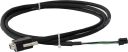
10 A External Battery Cable for CH150, CH200, CH201, PS150, or PS200
Orderable34031
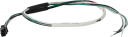
BP12 and BP24 10 A Battery Cable
Orderable18663
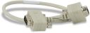
Null Modem Cable, 9-Pin PIn (Male) to 9-Pin Pin (Male)
Orderable20770
RS-232 Interface Cable for the PS200 or CH200
Orderable25356
Serial Interface Cable, PS200 or CH200 to Datalogger
Orderable39177
Status unavailable39642
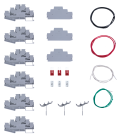
SDI-12 DIN Rail Terminal Bus Kit without Mounting Bracket
Orderable
Related Resources
Case Studies
Documents
- Manual
PS200/CH200 12 V Charging Regulators
December 2025
View Document - Brochure
CH200 Smart 12 V Charging Regulator
March 2026
View Document - Compliance
CH200, PS200, and 22238 EU Declaration of Conformity
September 2022
View Document - Compliance
CH200, PS200, and 22238 UK Declaration of Conformity
September 2022
View Document - View all documents