CWS900
CWS900
RetiredConfigurable900 MHz Configurable Wireless Sensor Interface
Pricing
- Model:
- CWS900
- Item Number:
- 26179
- Warranty:
- 1 year
- Lead time:
- 14 days
Overview
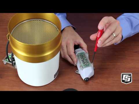
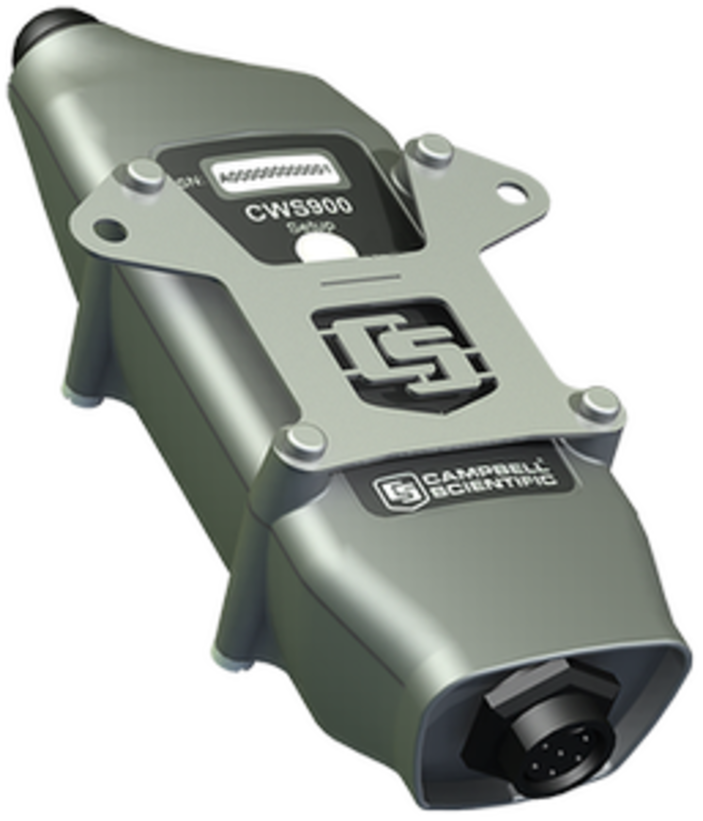
The CWS900 allows a sensor with a special connector to be used in a wireless sensor network; the special connector is available as an option for a large variety of sensors. (See the Compatibility information on the web page.)
The CWS900 contains an internal 900 MHz spread-spectrum radio that transmits data to the CWB100 Wireless Base Station or to another wireless sensor. The frequency of the CWS900's internal radio is commonly used in the US and Canada.
Key Advantages
Technical Description
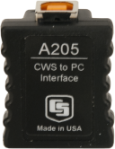
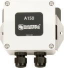
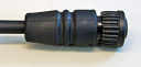
The CWS900 has a sealed connector for attaching one rain gage, wind sensor, temperature/RH probe, or another low power sensor. It measures analog voltages, low level AC, pulse counts, and can supply an excitation voltage for powering some sensors or making bridge measurements. The type of measurement that the sensor performs is configured using Wireless Sensor Planner, Network Planner, or DevConfig software. The CWS900 interfaces with the PC for configuration via the A205 CWS Sensor to PC Interface.
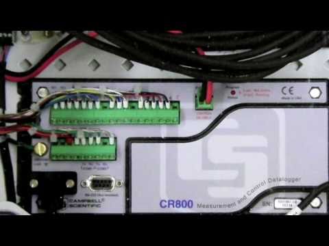
The CWS900 can route its transmissions through up to three other wireless sensors. A data logger is connected to the CWB100 base station for processing and storing the CWS900's data.
The CWS900 is battery powered using either alkaline batteries or a rechargeable battery and a solar cell.
Why Wireless?
There are situations when it is desirable to make measurements in locations where the use of cabled sensors is problematic. Protecting cables by running them through conduit or burying them in trenches is time consuming, labor intensive, and sometimes not possible. Local fire codes may preclude the use of certain types of sensor cabling inside of buildings. In some applications measurements need to be made at distances where long cables decrease the quality of the measurement or are too expensive. There are also times when it is important to increase the number of measurements being made but the data logger does not have enough available channels left for attaching additional sensor cables.
Note: The internal radio is not designed to move a lot of data quickly. It takes 15 to 30 seconds per hop when moving data from a sensor, through a sensor used as a repeater, and ending up at the base radio. Going through three repeaters could take a data packet anywhere from 45 to 90 seconds to get to the base radio.
Benefits
- Allows a wide variety of sensors to be used in a wireless network
- Internal frequency-hopping, spread-spectrum radio provides longer range and less interference
- Battery powered
- A reliable, low-maintenance, low-power method for making measurements in applications where cabled sensors are impractical or otherwise undesirable
- Transmissions can be routed through up to three other wireless sensors
Specifications
- Weather Resistance
- IP67 rating for sensor and battery pack
(Battery pack must be properly installed. Each sensor is leak tested.)
- Operating Temperature Range
- -25° to +50°C
- Operating Relative Humidity Range
- 0 to 100%
- Power Source
- 2 AA batteries with a battery life of 1 year assuming sensor samples taken every 10 minutes.
(Optional solar charging available.)
- Average Current Drain
- 300 μA
(with 15-minute polling and depending on attached sensor)
- Analog Channels
- SE1, SE2, SE3
(single-ended)
- Analog Channels
- DF
(differential)
- Analog Input Range
- -1 to +2.5 Vdc
- Resolution
- 0.3 μV
- Excitation Voltage
- 2.5 V, 3.3 V, 5.0 V
(20 mA maximum)
- Excitation Voltage Accuracy
- ±2%
(-35° to +70°C)
- Low-Level AC Input
- 20 mV minimum
(10 kHz maximum frequency)
- Temperature Accuracy
- ±0.2ºC
- Analog Measurement Accuracy
- ±(0.02% of reading + 2 µV)
(0° to 50°C)
- Analog Measurement Accuracy
- ±(0.05% of reading + 2 µV)
(-35° to +70°C)
- Bridge Measurement Accuracy (+2.5 V excitation only)
- ±(0.03% of reading + 3 µV)
(0° to 50°C)
- Bridge Measurement Accuracy (+2.5 V excitation only)
- ±(0.07% of reading + 3 µV)
(-35° to +70°C) Not including sensor and measurement noise, and external bridge resistor errors.
- Dimensions
- 15 x 6 x 4.5 cm
(5.9 x 2.4 x 1.77 in.)
- Weight
- 184 g
(6.5 oz)
Switch Closure
- Maximum Count Rate
- 100 Hz
- Minimum Open Time
- 5 ms
- Minimum Closed Time
- 5 ms
- Maximum Bounce Time
- 4 ms
- Maximum Number of Counts
- Records 1,000,000 counts before it rolls over.
Internal 25 mW FHSS Radio
- Frequency
- 902 to 918 MHz
- Where Used
- US and Canada
- FHSS Channel
- 50
- Transmitter Power Output
- 25 mW
(+14 dBm)
- Receiver Sensitivity
- -110 dBm
(0.1% frame error rate)
- Standby Typical Current Drain
- 3 μA
- Receive Typical Current Drain
- 18 mA
(full run)
- Transmit Typical Current Drain
- 45 mA
- Average Operating Current
- 15 μA
(with 1-second access time)
- Quality of Service Management
- RSSI
- Additional Features
- GFSK modulation, data interleaving, forward error correction, data scrambling, RSSI reporting
Related Resources
Documents
- Brochure
Campbell Wireless Sensor Network
October 2016
View Document - Brochure
CWS900 900 MHz Configurable Wireless Sensor Interface
March 2026
View Document - Manual
Wireless Sensor Network (CWB100, CWS220, and CWS900)
November 2017
View Document - Document
CWS-Series and CWB-Series Discontinuation Notice
February 2017
View Document