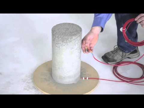
CDM-VW305
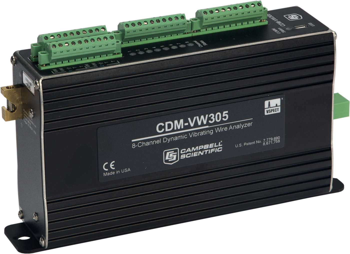
CDM-VW305
RetiredConfigurable8-Channel Dynamic Vibrating Wire Analyzer
Pricing
- Model:
- CDM-VW305
- Item Number:
- 29374
- Warranty:
- 1 year
- Lead time:
- 14 days
Overview
The CDM-VW305 is an eight-channel interface that you can use between standard single-coil circuit vibrating wire sensors and data loggers to allow shorter intervals between measurements. With the CDM-VW305 interface, you can achieve much faster and better measurements without having to purchase new sensors. Sensors typically used with the CDM-VW305 are strain gages, load cells, pressure transducers, crackmeters, and tiltmeters.
This interface uses an excitation mechanism that maintains the vibrating wire sensor in a continuously vibrating state. The interface measures the resonant frequency of the wire between excitations using the patented vibrating wire spectral-analysis technology (VSPECT™). VSPECT provides very fine measurement resolution and also limits the influence of external noise by discriminating between signal and noise based on frequency content. Because of this technology, the signal can be carried through longer cables, giving you flexibility in your sensor and data logger siting.
You can connect multiple CDM-VW305 modules to one data logger. The CDM-VW300 is similar to this item, but has two channels.
The dynamic vibrating wire measurement technique is protected under U.S. Patent No. 8,671,758, and the vibrating wire spectral-analysis technology (VSPECT) is protected under U.S. Patent No. 7,779,690.
Key Advantages
Vibrating Wire Measurements
Uses patented VSPECT® technology for noise immunity and industry-leading quality
Technical Description
In addition to the dynamic vibrating wire measurement, the CDM-VW305 makes several auxiliary measurements. A static vibrating wire measurement is made once each second, along with the dynamic measurements, which provides finer measurement resolution and greater immunity to external noise sources. The CDM-VW305 includes a thermistor input channel paired with each vibrating wire channel, featuring high-precision 24-bit measurements at a 1 Hz rate. Lastly, a rich set of diagnostic parameters is provided with the vibrating wire data.
The CDM-VW305 has the capability to simplify post-processing of data by computing common values internally. Vibrating wire data can be reported as measured frequency or as the frequency squared with a multiplier and offset applied. The thermistor data is reported as resistance or is converted to degrees Celsius using the thermistor’s Steinhart-Hart coefficients. The CDM-VW305 also can internally compile rainflow histograms from the final data and report the values at user-specified intervals.
Vibrating Wire Inputs
Each channel has two terminals for connecting to the coil of the vibrating wire sensor. Both vibrating wire terminals are labeled VW and the polarity of the wiring is arbitrary. The sensor is excited and measured through the same connections. Sinusoidal excitation is applied for a few cycles of the wire oscillation. The wire is maintained in a continuously vibrating state. Excitation voltage varies automatically to maintain the desired return signal strength.
Thermistor Inputs
Each channel has two terminals for connecting to the thermistor. Both thermistor terminals are labeled T and the polarity of the wiring is arbitrary. The measurement is a half-bridge configuration with the excitation circuitry and completion resistor integrated into the module.
Benefits
- Interfaces to standard single-coil vibrating wire sensors
- Eight simultaneously sampled channels per module; synchronizable across multiple modules
- Dynamic measurement rates of 20 to 333 Hz
- Static measurement at 1 Hz made simultaneously with the dynamic measurement
- Spectral interpolation approach provides superior noise immunity and measurement resolution compared to time-domain period-averaging approach
- Excitation method provides frequent low-energy pulses to maintain a continuous resonant vibration in the sensor
- Thermistor input for each vibrating wire channel is sampled at 1 Hz
- Data logger communications via CPI
- User-configurable, onboard post-processing of the data including frequency output conversion, temperature conversion, and rainflow histogram collection
Specifications
- -NOTE-
- Electrical specifications are valid over a -40° to +70°C range, non-condensing environment, unless otherwise specified. Extended electrical specifications are valid over a -55° to +85°C range in a non-condensing environment.
- Scan Rates
- 20, 50, 100 Hz
- CPI Baud Rate
- Selectable from 25 kbps to 1 Mbps
- Input Resistance
- 5 kΩ
- Excitation Voltage Range
- 0 to ±3 V
(6 V peak-to-peak)
- Excitation Voltage Resolution
- 26 mV
- Operating Temperature Range
- -40° to +70°C
(standard)
- Operating Temperature Range
- -55° to +85°C
(extended)
- Measurement Frequency Accuracy
- ±(0.005% of reading + measurement resolution)
- Sustained Input Voltage without Damage
- -0.5 to +7.1 V
- Number of Channels
- 8
- USB
- USB 2.0 full speed connection is available for attaching the device to a PC.
(This port is provided to configure the module, send updates, and communicate with the Dynamic Vibrating Wire Toolbox software. The USB port is not provided for use within a permanent data collection system.)
- CPI
- Used for connection to the data logger. Baud rate selectable from 50 kbps to 1 Mbps.
(Allowable cable length varies depending on baud rate, number of nodes, cable quality, and noise environment, but can be as long as 2,500 ft under proper conditions.)
- Mounting
- Standard 1-in. grid
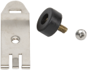
(Optional DIN rail mounting available.)
- Warranty
- One year against defects in materials and workmanship
- Dimensions
- 20.3 x 12.7 x 5.1 cm
(8 x 5 x 2 in.)
Measurement Resolution at Sample Rates
- -NOTE-
- Typical values for a 2.5 kHz resonant sensor
- 1 Hz Sample Rate
- 0.005 Hz RMS
(noise level)
- 20 Hz Sample Rate
- 0.008 Hz RMS
(noise level)
- 50 Hz Sample Rate
- 0.015 Hz RMS
(noise level)
- 100 Hz Sample Rate
- 0.035 Hz RMS
(noise level)
- 200 Hz Sample Rate
- 0.11 Hz RMS
(noise level)
- 333.3 Hz Sample Rate
- 0.45 Hz RMS
(noise level)
Sensor Resonant Frequency Range
- 20 Hz Sample Rate
- 290 Hz
(minimum sensor frequency)
- 20 Hz Sample Rate
- 6000 Hz
(maximum sensor frequency)
- 50 Hz Sample Rate
- 290 Hz
(minimum sensor frequency)
- 50 Hz Sample Rate
- 6000 Hz
(maximum sensor frequency)
- 100 Hz Sample Rate
- 580 Hz
(minimum sensor frequency)
- 100 Hz Sample Rate
- 6000 Hz
(maximum sensor frequency)
Thermistor
- Completion Resistor
- 4.99 kΩ 0.1%
- Excitation Voltage
- 1.5 V
- Resolution
- 0.002 Ω RMS
(@ 5 kΩ thermistor resistance)
- Accuracy
- 0.15% of reading
(Thermistor accuracy and resistance of the wire should be considered as additional errors.)
- Measurement Rate
- 1 Hz
Power Requirements
- Voltage
- 9.6 to 32 Vdc
- Typical Current Drain
- 190 mA
(@ 12 Vdc)
Accessories
(12)29370
CPI Network Kit
Orderable27555
USB 2.0 Cable, Type A Pin (Male) to Micro B Pin (Male), 6/6.5 ft
Orderable29796
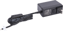
1.67 A 24 V Power Supply
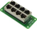
RetiredHUB-CPI
8-Channel RJ45 Hub for CPI Peripherals
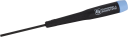
Orderable8125
Flat-Bladed Screwdriver, 2.5 mm Blade x 50 mm Shaft
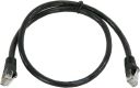
Orderable28899
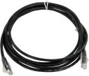
CAT6 Ethernet Unshielded Cable with RJ45 Connectors, 2 ft
Orderable28900
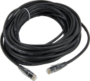
CAT5e Ethernet Unshielded Cable with RJ45 Connectors, 10 ft
Orderable28901
CAT5e Ethernet Unshielded Cable, RJ45 to RJ45, 50 ft
OrderableCAT5UCBL
Unshielded CAT5e Cable with RJ45 Connectors
Retired29388
CDM DIN-Rail Mounting Kit
Orderable28558
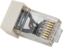
Modular RJ45 Resistor Termination Plug for CPI Bus
Orderable39177
1.67 A 24 Vdc Power Supply
Orderable

Related Resources
Case Studies
Documents
- Brochure
CDM-VW300 Series Dynamic Vibrating Wire Measurement Modules
View Document - Compliance
CDM-VW300 and CDM-VW305 EU Declaration of Conformity
May 2016
View Document - Manual
CDM-VW300 Series Dynamic Vibrating Wire Analyzer System
January 2020
View Document - Brochure
CDM-VW305 8-Channel Dynamic Vibrating Wire Analyzer
March 2026
View Document - View all documents