AM16/32B
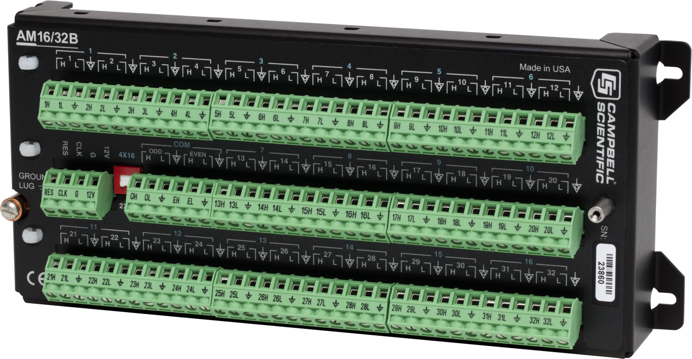
AM16/32B
OrderableConfigurableGSA16- or 32-Channel Relay Multiplexer
Pricing
Configuration
Sign in for option pricing- 25 to +50CAM16/32B-ST
- 55 to +85CAM16/32B-XT
Select a configuration to add to your quote
- Model:
- AM16/32B
- Item Number:
- AM16/32B
- Warranty:
- 1 year
- Lead time:
- 14 days
Overview
The AM16/32B multiplexer significantly increases the number of sensors that you can measure with a Campbell Scientific data logger. It interfaces with the data logger and adds terminals so that you can wire additional sensors of almost any type.
Key Advantages
Connects many sensors to single data logger
Technical Description
Depending on sensor type, the AM16/32B can multiplex 16, 32, or 48 sensors. Up to six AM16/32Bs may be connected to the same data logger, depending on the number of control ports and analog inputs available.
The AM16/32B either multiplexes 16 groups of four lines (a total of 64 lines) through four common (COM) terminals. Alternatively, a manual switch setting allows the AM16/32B to multiplex 32 groups of two lines (also a total of 64 lines) through two COM terminals. A cable connects the common terminals to data logger analog inputs, excitation channels, or ground as required by the sensor. The data logger controls the multiplexer using two control ports, or one control port and one excitation channel.
Electrical Surge Protection
The equipment is protected from electrical surges using gas tubes on all inputs. A 35 V varistor is connected between the shield ground and ground lug to provide surge protection. The Reset, Clock, and +12 V terminals are protected by 18 V TVS diodes.
Benefits
- Significantly increases the number of sensors the data logger can measure
- Can multiplex 16, 32, or 48 sensors
- Supports many types of sensors including thermistors, potentiometers, strain gages, vibrating wires, reflectometers, and soil moisture blocks
- Decreases the cost of cabling individual sensors on long wire runs
- Allows a relay address to be used to go directly to a specific channel—reducing power consumption and wear on the relay switches
- Electrical surge protection via gas tubes on all analog I/O, and varistors or TVS diodes on all other connections
- Prevents sensor-cable damage by providing strain relief for sensor leads and independent routing for sensor shield lines
- Eliminates the requirement for dc blocking capacitors for gypsum soil moisture blocks, significantly reducing sensor cost
Specifications
- -NOTE-
- The protection on the reset, clock, and +12 V inputs are provided by 18 V TVS diodes.
- Power
- Unregulated 9.6 to 16 Vdc
- Scan Advance
- Occurs on the leading edge of the clock pulse transition
(from below 1.5 V to above 3.3 V)
- Minimum Clock Pulse Width
- 1 ms
- Maximum Actuation Time for Relay
- 20 ms
- Relay Operation
- Break before make
- Initial Relay Resistance, Closed
- 0.1 ohm
- Maximum Switching Current
- 500 mA
(Switching currents greater than 30 mA [occasional 50 mA current is acceptable] will degrade the contact surfaces of the mechanical relays and increase their resistance.This will adversely affect the suitability of these relays to multiplex low voltage signals.Although a relay used in this manner no longer qualifies for low voltage measurement, it continues to be useful for switching currents in excess of 30 mA.) - Maximum Switching Voltage
- 50 Vdc
A voltage divider such as the VDIV10:1 may be needed between the AM16/32B and the data logger to stay within the input limits of the data logger channel. - Minimum Contact Life
- 5 x 10⁷ operations
- Maximum Contact Voltage Rating
- 70 V
- Maximum Voltage
- 8 Vdc
(clock level)
- CE Compliance
- EN 61326:1998
- CE Compliance
- EN 55022:1998 Class B
- Surge
- Complies with IEC61000-4-5, test level 3
(±2 kV, 2 ohm coupling impedance)
- Operating Temperature Range
- -25° to +50°C
(standard)
- Operating Temperature Range
- -55° to +85°C
(extended)
- Dimensions
- 23.9 x 10.2 x 4.6 cm
(9.4 x 4.0 x 1.8 in.)
- Weight
- ~680 g
(~1.5 lb)
ESD
- Air Discharge
- Complies with IEC61000-4-2, test level 4 (±15 kV).
- Contact Discharge
- Complies with IEC61000-4-2, test level 4 (±8 kV).
Typical Current Drain
- Quiescent
- < 210 µA
- Active
- 6 mA
(typical in 2x32 mode)
- Active
- 11 mA
(typical in 4x16 mode)
Reset Levels
- Inactive
- < 0.9 V
- Active
- 3.3 to 8 V

Related Resources
Case Studies
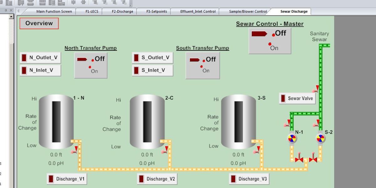
New Mexico: SCADA System
Replacing an existing SCADA system
Albuquerque, New Mexico, USA
May 4, 2017
View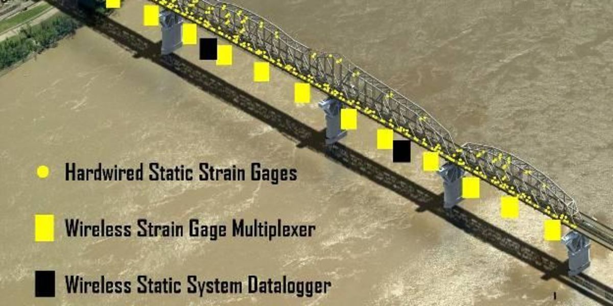
Louisiana: Monitoring Bridge Expansion
Monitoring bridge stresses during widening
New Orleans, Louisiana
June 3, 2010
View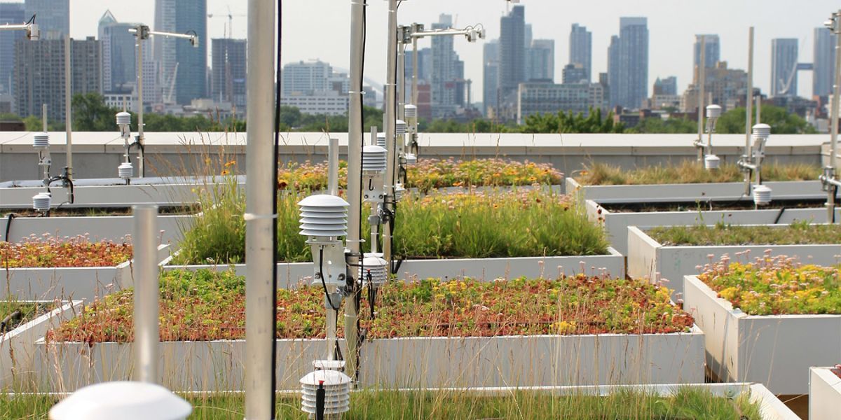
Ontario: Green Roofs
Monitoring conditions to test and evaluate the construction standards of green roofs
Toronto, Ontario, Canada
July 15, 2015
View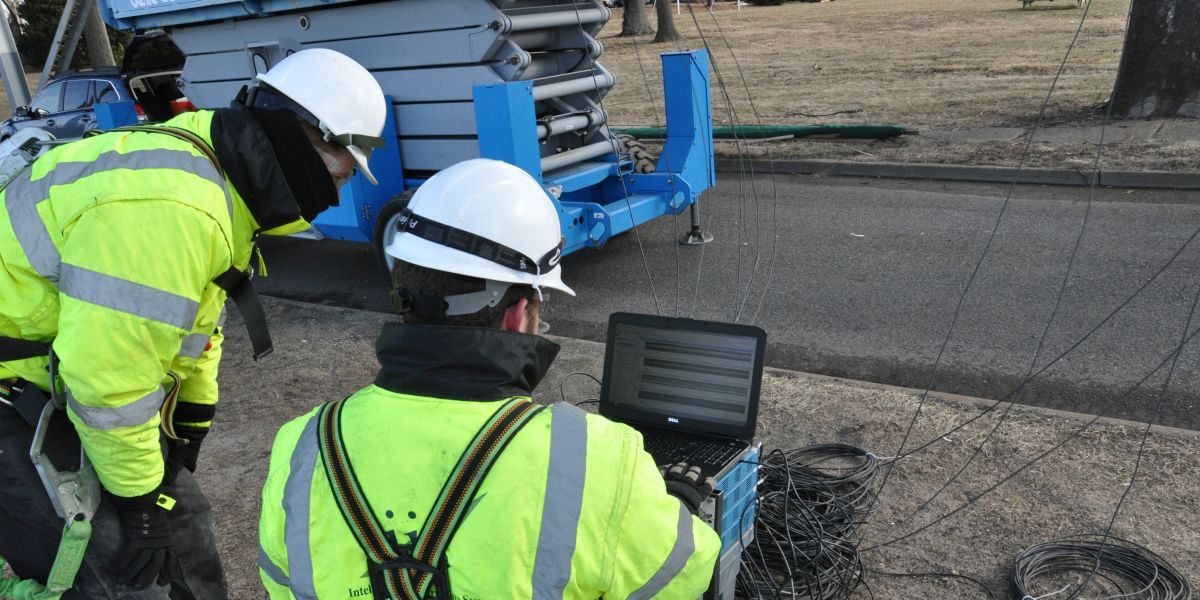
Delaware River: Bridge Health
Structural health monitoring
Bristol, PA; Burlington, NJ
December 29, 2017
View- View all case studies