SDM-IO16
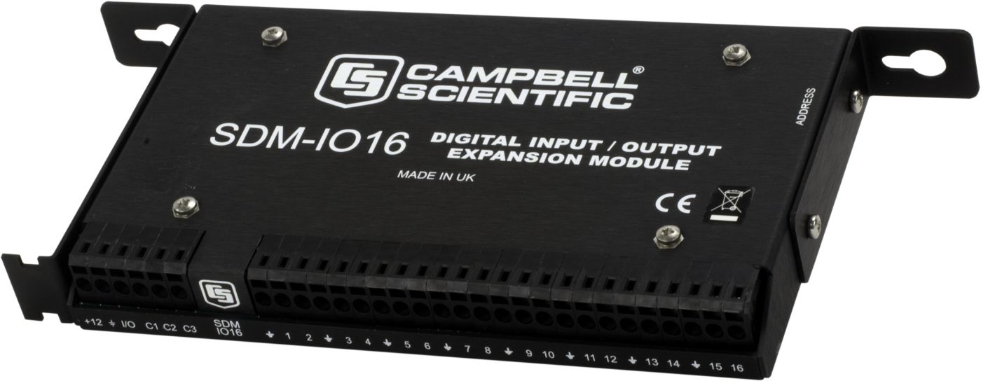
SDM-IO16
Retired16-Channel Input/Output Module
Pricing
- Model:
- SDM-IO16
- Item Number:
- 16502
- Warranty:
- 1 year
Overview
The SDM-IO16 expands the digital input and output channel count of Campbell Scientific data loggers.
Key Advantages
Technical Description
The SDM-IO16 expands the digital input and/or output capability of Campbell Scientific data loggers. When a port is configured as an input, each port can monitor logic state, count pulses, measure signal frequency, and determine duty cycle. An option in the pulse counting mode enables switch debounce filtering, allowing the SDM-IO16 to accurately count switch closures. The SDM-IO16 can also be programmed to send an interrupt signal to the data logger when one or more input signals change state.
When configured as an output, each port can be set to 0 or 5 V by the data logger. A boost circuit allows an output that is set HI to source a current of up to 100 mA (at a reduced output voltage) for controlling external devices such as low voltage valves or relays.
Up to 15 SDM-IO16 modules can be addressed allowing up to 240 ports to be controlled by the data logger.
Data Logger Connection
The SDM Jumper Wire Kit (pn 32505) connects up to four SDMs to the data logger. This kit is recommended when multiple SDMs are connected to one data logger or for extremely short distances between the SDM and data logger. The CABLE5CBL-L cable is recommended for connecting a single SDM to the data logger, and for longer distances between the SDM and data logger.
Benefits
- Provides 16 digital I/O ports
- When configured as an input, each port can monitor logic state, count pulses, measure signal frequency, and determine duty cycle
Specifications
- Function
- Expands the digital input and/or output capability of a data logger.
- Number of Channels
- 16
- Operating Temperature
- -25° to +50°C
- SDM & I/O Port
- 0/5 V logic level ports
(for connecting to the datal ogger’s control/SDM ports)
- EMC Status
- Complies with EN 61326:1997.
- Operating Voltage
- 12 Vdc
(nominal 9 to 18 V)
- Minimum Frequency
- 0 Hz is reported if there are less than two high-to-low signal transitions in the measurement interval.
- Minimum Pulse Width
- 244 μs
- Default Switch Debounce Timing
- Input and ground must remain closed for 3.17 ms then remain open for 3.17 ms to be counted as a closure.
- Internal Clock Accuracy
- ±0.01%, worst case
(-25° to +50°C)
- Maximum Pulse Measurement Interval
- 15.9375 s
- Dimensions
- 23.0 x 10.0 x 2.4 cm
(9 x 4 x 1 in.)
- Weight
- 350 g
(12 oz)
Maximum Frequency (with 50/50 duty cycle)
- Switch Debounce-Mode Turned Off
- 2.0 kHz on all channels simultaneously
- Default Switch Debounce-Mode Enabled
- 150 Hz on all channels
Current Drain
- -NOTE-
- Current consumption is roughly proportional to input signal frequency and number of ports used.
Current drawn from any output must be added to the quiescent level to obtain the total current drain.
- Typical Standby
- 600 µA
(all ports high, no load, excludes pulse counting)
- Maximum
- 3 µA
(active with all 16 ports counting pulses at 2 kHz and no output load)
Output
- ON/HI Voltage (no load)
- 5 V
(nominal)
- ON/HI Voltage (no load)
- 4.5 V
(minimum)
- OFF/LO Voltage (no load)
- 0 V
(nominal)
- OFF/LO Voltage (no load)
- 0.1 V
(maximum)
- Sink Current
- Output will sink 8.6 mA from a 5 V source.
- Source Current
- 42 mA
(@ 3 V)
- Source Current
- 133 mA short-circuited to ground
Input
- Voltage
- 4.0 V minimum threshold
(high)
- Voltage
- 1.0 V maximum threshold
(low)
- Protection
- Input clamped at -0.6 V and ±5.6 V relative to ground
(via a 33 Ω resistor to withstand a continuous current flow of 200 mA)
- Source Current
- Output will source 42 mA at 3 V.
- Source Current
- 133 mA short-circuited to ground
- Impedance
- Biased to +5 V relative to ground
(by a 100 kohm resistor)