
Did you know that you can turn your Campbell Scientific data logger into a Modbus TCP/IP server? Do you know why that’s a good idea? Campbell Scientific data loggers are commonly used as Modbus server devices. This means that the data logger is configured to implement the Modbus communications protocol and listen for Modbus polls from a Modbus client, such as a SCADA (supervisory control and data acquisition) system. Turning your data logger into a Modbus TCP/IP server is a great way to allow systems that use the Modbus protocol to have access to your live measurement data.
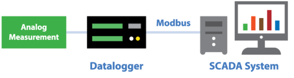
To better understand how this works, we’ll go through an example exercise to show the basic concepts of how to implement the Modbus protocol on a CR1000 datalogger. We’ll use a CR1000 datalogger connected to a SCADA system. You may remember our previous discussion about SCADA systems and Modbus from the “Why Modbus Matters: An Introduction” blog article.
Getting Started
In our example, the CR1000 is programmed to measure battery voltage, panel temperature, and an analog measurement in a simple program as shown below:
'Program for a CR1000 Series Datalogger 'Declare Public Variables Public PTemp, batt_volt, analog_meas 'Data Table Definition DataTable (Table1,1,-1) DataInterval (0,10,Min,10) Minimum (1,batt_volt,FP2,0,False) Average (1,PTemp,FP2,False) Average (1,analog_meas,FP2,False) EndTable 'Main Program BeginProg Scan (1,Sec,0,0) 'Measure the datalogger panel temperature PanelTemp (PTemp,250) 'Measure the battery voltage Battery (batt_volt) 'Measure an analog voltage VoltSe (analog_meas,1,mV5000,1,1,0,_60Hz,1.0,0) 'Call final storage table CallTable Table1 NextScan EndProg
Modbus Programming
The CR1000 datalogger in our example is connected to a SCADA system using an NL121 Ethernet Interface. Therefore, we need to program our data logger to listen to Modbus polls on the appropriate communications port and to respond with our most current measured data. To do this, we need to use the ModbusServer() instruction, declare a variable array to hold our Modbus data, and then update that array with our measurements.
This is accomplished using the code below:
'Program for a CR1000 Series Datalogger 'Declare Public Variables Public PTemp, batt_volt, analog_meas Public ModbusRegisters(3) Public ModbusCoil As Boolean 'Data Table Definition DataTable (Table1,1,-1) DataInterval (0,10,Min,10) Minimum (1,batt_volt,FP2,0,False) Average (1,PTemp,FP2,False) Average (1,analog_meas,FP2,False) EndTable 'Main Program BeginProg 'Configure the datalogger as a Modbus Server ModbusServer (502,0,1,ModbusRegisters(),ModbusCoil,2) Scan (1,Sec,0,0) 'Measure the datalogger panel temperature PanelTemp (PTemp,250) 'Measure the battery voltage Battery (batt_volt) 'Measure an analog voltage VoltSe (analog_meas,1,mV5000,1,1,0,_60Hz,1.0,0) 'Populate Modbus Registers ModbusRegisters(1) = PTemp ModbusRegisters(2) = batt_volt ModbusRegisters(3) = analog_meas 'Call final storage table CallTable Table1 NextScan EndProg
A Closer Look
Let’s take a closer look at the ModbusServer() instruction we added to the program code. The instruction is added between the BeginProg and Scan statements. The ModbusServer() instruction is placed between these two statements because it only needs to execute once at compile time rather than being executed during each scan.
The ModbusServer() instruction contains six parameters as shown below:
ModbusServer (COMPort,BaudRate,ModbusAddr,ModbusVariable,BooleanVar,ModbusOption)
For reference, in our program code, our instruction with the parameters looks like this:
ModbusServer (502,0,1,ModbusRegisters(),ModbusCoil,2)
Let’s take a closer look at those parameters and what they mean:
- COMPort: This parameter defines the communications port over which the data logger listens for Modbus polls. In our example, we use 502, because we are using an Ethernet connection and 502 is the default Modbus TCP port.
- BaudRate: We use this parameter to set the baud rate of the communications port. In our example, this parameter (0) is ignored because our communications are over an Ethernet connection.
- ModbusAddr: This parameter sets the Modbus address (or device ID) of the data logger. In our example, we set our data logger to have an address of 1.
- ModbusVariable: We use this parameter to define the Modbus Register Map of our data logger. (A Modbus Map defines the register addresses for the available data.)
Measurements stored in this array are used as Modbus Input and Holding registers. (A register is a 16-bit memory location.) The data logger does not distinguish between input and holding registers. Because we have declared our ModbusVariable as a floating point number (32 bits), it will be spread across two Modbus Registers (16 bits in each). In our example, our Modbus Map looks like this:
Modbus Registers Measurement Description Units 1,2
Data Logger Panel Temperature
Degrees Celsius
3,4
Data Logger Battery Voltage
Volts
5,6
Analog Measurement
Millivolts
- ModbusBooleanVar: This parameter is used to define a Modbus Coil Map and holds the result if a Modbus client device sends a discrete on/off command to the data logger (that is, 01 Read Coil/Port Status, 02 Read Input Status, 05 Force Single Coil/Port, 15 Force Multiple Coils/Ports).
If a 0 is entered for this parameter, the discrete commands are mapped to the data logger control ports C1 to C8, and a compile warning is generated. In our example, I have created a variable to act as a coil. - ModbusOption: This is an optional parameter that defines the data type of the Modbus variables and the byte order. In our example, I have chosen to format our Modbus Map floating point variables with the byte order ABCD.
Conclusion
The example exercise above outlines how you can accomplish a simple Modbus TCP/IP server implementation by programming a CR1000 datalogger in CRBasic. Please note that the Short Cut program generator also has the capability to generate the code we have discussed above. By taking advantage of the concepts shown above, you can add more measurements to your program, as well as to the Modbus Register Map of your data logger. The result is that your SCADA system can access live measurement data for a more complete weather station implementation.
You can look forward to blog articles in the future with more details on specific Modbus topics, common pitfalls, and best practices. In the meantime, share any Modbus comments or questions you have below.